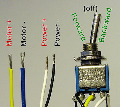
The fact that the drivers switch operates the window properly lets you know that the window components all function properly as that the problem is probably electrical. A technician that is diagnosing this would use the wiring diagram to find the proper wires to test and check for power when the window is rolled up to see if there is power. 2 - Auto Park switch. 4 - Auto Park +ve supply. How does it work. Flicking the toggle switch to the first position (slow operation), power is applied to the relay, closing the contact and supplying power to pin 5 on the wiper motor (via pin 87 and 30 on the relay).
The alternate 3-way switch wiring configuration (California or West Coast) was used as a way to wire 3-way switches and be able to supply line voltage to either switch. This configuration is no longer allowed as the neutral is not present in each switch box.
Conventional 3-way wiring is not very complex. With conventional wiring, the line (line voltage) connects to the common of one switch, while the load (light) connects to the common of the other switch. However this alternate wiring configuration could cause confusion.
Alternate 3-way wiring configuration is described below.
Contexts 3 5 3 – Fast Window Switcher Wiring Schematic
- A traveler terminal from each switch are connected together.
- A common terminal from one switch and the other traveler terminal from the other switch are connected together and connect to the line voltage.
- The remaining common and traveler terminals on each switch are connected together and connect to the load(s).
It may be difficult to determine which configuration is present in any 3-way wiring configuration. When replacing a switch, the new switch needs to be connected the exact same way as the old one. If you have any problems with your 3-way switches, it may be best to call an electrician.
-->The scheduler maintains a queue of executable threads for each priority level. These are known as ready threads. When a processor becomes available, the system performs a context switch. The steps in a context switch are:
- Save the context of the thread that just finished executing.
- Place the thread that just finished executing at the end of the queue for its priority.
- Find the highest priority queue that contains ready threads.
- Remove the thread at the head of the queue, load its context, and execute it.
The following classes of threads are not ready threads.
- Threads created with the CREATE_SUSPENDED flag
- Threads halted during execution with the SuspendThread or SwitchToThread function
- Threads waiting for a synchronization object or input.
Contexts 3 5 3 – Fast Window Switcher Wiring Diagram
Until threads that are suspended or blocked become ready to run, the scheduler does not allocate any processor time to them, regardless of their priority.
The most common reasons for a context switch are:
- The time slice has elapsed.
- A thread with a higher priority has become ready to run.
- A running thread needs to wait.
Contexts 3 5 3 – Fast Window Switcher Wiring Harness
When a running thread needs to wait, it relinquishes the remainder of its time slice.
